Today, sea mariners experience a task no less daunting than
that of their predecessors of yesteryear on wooden ships fighting worm
infestations and wood rot. It was not long after the very first iron clad ship
was launched in 1843 that seafarers discovered a new enemy; corrosion. For
nearly two centuries, fleets around the globe have struggled with ways to
combat corrosion. It takes a great deal of time and money to stay on top of
corrosion on modern steel ships.
Stakeholders have taken an advanced approach to identify
corrosion early on to aid in determining the extent and repetitive time
intervals between restoration periods. They have determined the proper
intervals for a complete ship Corrosion Assessment. The Corrosion Assessment is
an in-depth evaluation of a ship’s hull and structural condition focused on
known problem areas within the ship’s class. The Corrosion Assessment Report
documents as found conditions and provides recommended solutions based on the
American Bureau of Shipping’s (ABS) Inspection Grading Criteria for their Hull
Inspection and Maintenance Program (HIMP). The six criteria covering the
various aspects of a hull and structural assessment are documented based on a
traffic light point rating system (0 through 6 scale – described below).
Provisions within the report provide grading for each space assessed, as well
as any equipment and/or systems within the space where undocumented or revised
preservation requirements are observed. Recommended preservation or repair
requirement solutions are documented, along with specific area and location
data. Additionally, Work Requests are automatically produced for each space,
equipment, or system that a preservation or repair recommendation has been
made. These Work Requests are considered new work also known as repairs for the
ship to correct and allow stakeholders to track to completion.
Corrosion Assessments Are Now Conducted Using SIP
A visual inspection is the primary method performed unless extensive coating, deformation, or fractures influence the need for a thorough localized inspection of the area concerned. All areas assessed are documented using a new Ship Inspection Program (SIP) application on a tablet, which allows the assessor to annotate condition, collect objective quality evidence, categorically grade the condition, provide recommendations, take pictures, and write Work Requests while on location. Using SIP all assessments and Work Requests with attached Objective Quality Evidence (OQE) are uploaded to any maintenance management system, while a final report is generated for assimilation. The Corrosion Assessment utilizes the HIMP scoring system to provide a means of determining the extent of corrosion, severity, and a method of monitoring conditions over any given time. Additionally, the conditions provided are to aid managers in planning work for future availability periods, the scoring helps to determine what locations require immediate attention and those that can be planned for a follow-on availability, also known as a period for ship repairs.
SIP for Corrosion Assessment, Detecting and Collecting
Using SIP technology, an inspection team will be able to thoroughly screen the entire ship, locate issues and collect related data in an efficient and effective manner. The SIP procedure for conducting a Corrosion Assessment contains all the ship’s spaces and equipment. The SIP tablet is a handheld portable device enabling the inspector to type in or vocalize findings. Additionally, the inspector can take pictures using the installed camera to provide OQE for assimilation and generating Work Requests.
HIMP: Grading the Condition
There are six criteria covering distinct aspects and conditions of the Corrosion Assessment. These are documented based on a traffic light point rating system (0 through 6 scale) on each compartment, space, or equipment. The score assigned in the SIP Work Request will denote the condition as GOOD, FAIR, or POOR. HIMP scoring is explained in detail below.
COATING
Good
0 —
Excellent coating with negligible indications of coating failure.
1 —
Minor spot rusting.
2 —
Spot rusting without visible coating failure is < 3% of the area under Consideration. Rusting is < 20% of edges or weld lines.
Fair
3 —
Breakdown of coating or rust penetration is > 3% but < 10% of the area. Hard rust scale is < 5% of the area. Rusting in the area is > 20% but < 35% of edges or weld lines.
4 —
Breakdown of coating or rust penetration is > 10% but < 20% of the area. Hard rust scale is > 5% of the area but < 10% of area. Rusting in the area is > 35% but < 50% of edges or weld lines.
Poor
5 —
Breakdown of coating or rust penetration is > 20% but < 30% of the area. Hard rust scale is > 10%
of the area but < 20% of area. Rusting in the area is > 50% but < 75% of edges or weld lines.
6 —
Breakdown of coating or rust penetration is > 30% of the area. Hard rust scale is < 20% of the
area. Rusting in the area is > 75% of edges or weld lines.
CORROSION
Good
0 —
No Rusting.
1 —
Negligible rusting / corrosion < 5% light rust.
2 —
Minor spot rusting < 20% light rust.
Fair
3 —
Local breakdown at edges of stiffeners and weld connections and/or light rusting over 20% or more of zone, > 20% light rust > 5% hard scale.
4 —
Hard scale at 10% or more of zone.
Poor
5 —
Serious/significant corrosion: More than 30% corrosion and active scale is present. Active scale is
loose or has fallen off the structure.
6 —
Extensive area of corrosion: Corrosion of hard and/or loose scale, including pitting, over 70% or more of the plating surface in question accompanied by evidence of thinning.
PITTING OR GROOVING
Good
0 —
No Pits or Grooves.
1 —
Shallow Pits or Grooves, Depth less than 1/3 of original thickness, Intensity % of zone < 5%.
2 —
Shallow Pits or Grooves, Depth less than 1/3 of original thickness, Intensity % of zone < 15%.
Fair
3 —
Shallow Pits or Grooves, Depth less than 1/3 of original thickness, Intensity % of zone > 15%.
4 —
Shallow Pits or Grooves, Depth less than 1/3 of original thickness, Intensity % of zone < 20%.
Poor
5 —
Shallow Pits or Grooves, Depth less than 1/3 of original thickness, Intensity % of zone > 20%.
6 —
Shallow Pits or Grooves, Depth less than 6mm of original thickness < 20%.
DEFORMATION
Good
0 —
No Deformation.
1 —
Within area/panel < 75mm (3 in) in depth.
2 —
Within area/panel > 75mm (3 in) in depth.
Fair
3 —
Within area/bay < 75mm (3 in) in depth, set-in with associated internals tripped.
4 —
Tripped and buckled internals and brackets.
Poor
5 —
Within area/bay < 75mm (3 in) in depth, set-in with associated internals tripped.
6 —
Tripped and buckled internals and brackets.
FRACTURES
Good
0 —
No Fractures.
Fair
3 —
Weld fractures in support brackets, internals and/or detachments.
3 —
Fractures in flanges of brackets, internals and/or stiffeners.
4 —
Fractures in webs of frames, floors, brackets, stiffeners and/or internals.
Poor
5 —
Fractures in transverse and longitudinal bulkheads and/or primary structure members.
6 —
Fractures in hull envelope side shell, bottom and/or deck.
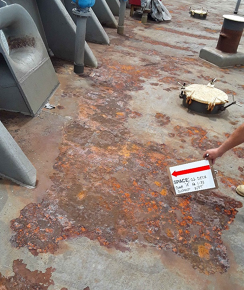
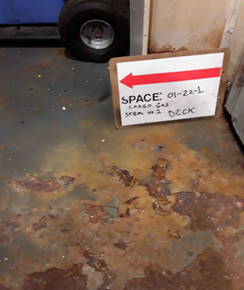
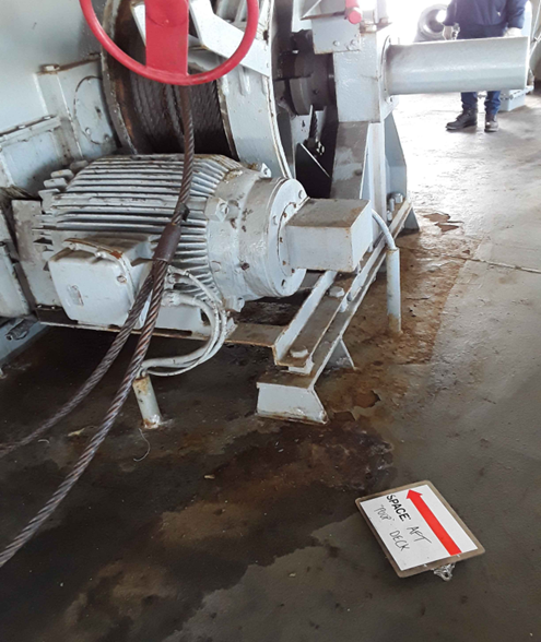
As evidence, the inspector took photographs of what he found during the inspection:
Objective Quality Evidence (OQE): See for Yourself
In 1918 a San Antonio newspaper advertisement paraphrased a
quote attributed to Arthur Brisbane “One picture is worth a thousand words”.
The phrase is no less true today. Photos provide a manager or planner a deeper
understanding of what the inspector has found, and that his/her words may not
have adequately described. Using SIP, an inspector can take photographs with
the tablet while in the space or looking at equipment and writing the
assessment. Photos are automatically attached to the assessment on the tablet
and uploaded as a new Work Request into any mantainenace management system. No
less than two photos are taken for each discrepancy and attached to the Work
Request.
Work Request: Who, What, Where, and When
Using SIP, a complete and concise Work Request is produced
for every deficiency and uploaded into any maintenance management system for
the ship that was assessed. Each Work Request with minimum of two pictures
attached annotates the condition found grading, recommended actions, the
location, the square footage or inches, metal replacement if required, and area
of ultrasonic testing if required.
SIP: The Right Tool for Today’s Inspection and Maintenance Tasks
SIP technology is an inspection tool to improve age-old
practices, it enhances the ability to collect data, provide information, and
insert objective quality evidence, all while on location. It allows the
inspector to freely maneuver about the vessel completing an entire inspection
without having to sit behind a computer annotating notes, downloading pictures,
writing, uploading Work Requests into SAMM, and compiling a consolidated
report. The SIP program is currently being used to conduct any type of
inspection related acitivites.